Loki contains a universal BGP module, written in python. It implements the most common used BGP packet and data types and can be used to establish a connection to a BGP speaking peer. Once a connection is established, the tool starts a background thread which sends keep-alive packages to hold the connection established and the published routes valid. To publish BGP routing information the module provides built-in data types which can be merged to the appropriated update statement. Once an update statement is set up it can be sent once or multiple times to the connected peer. It is possible to use kernel based MD5 authentication, as described in RFC2385. Another module makes it possible to brute force the used MD5 authentication key.
An Example for Injecting IPv4 Routing Information
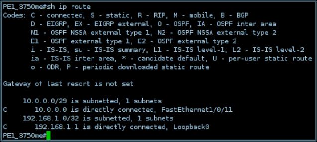
The peer is a Cisco 3750ME with a (pre-attack) routing table looking like this:
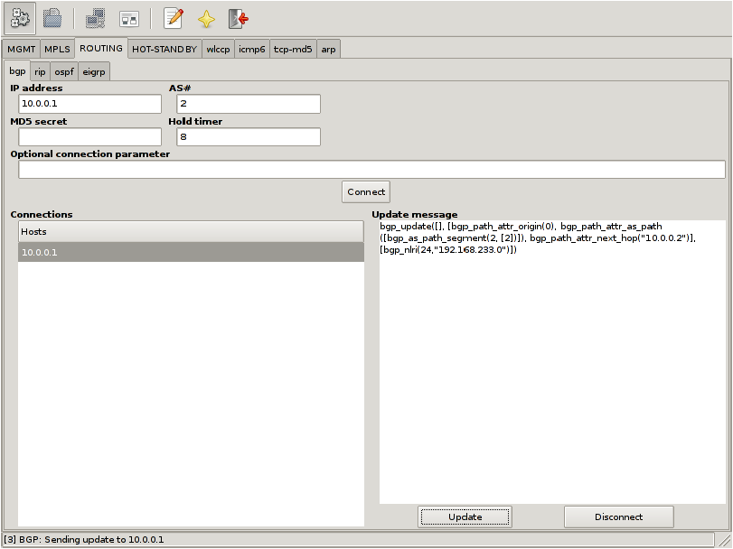
Loki is then used to inject IPv4 routing information:
The first step is to configuring the target IP address, the autonomous system number 2 and a hold timer of 8 seconds. Afterwards the session can be established by clicking on the “Connect” button. If Loki is able to establish the connection, a background keep alive thread is started, which sends an BGP keep alive packet every hold time / 4 seconds.
The next step is to configure the BGP update message, which defines, the routing information to publish to the connected host. In the example case I build up a RFC1771 IPv4 routing BGP update packet which says I am announcing the network 192.168.233.0/24 and traffic for this network should be forwarded to the IP address 10.0.0.2 which is my target host.
In the end I send the prepared update packet out by selecting the designated host from the connection list and clicking the “Update” button.
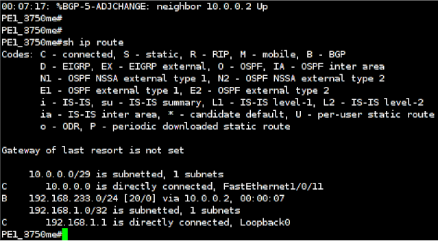
After publishing the routing information, the router’s routing table looks like this:
So, I successfully injected a route to the network 192.168.233.0/24 which, in this case, directs all matching traffic to my target host.
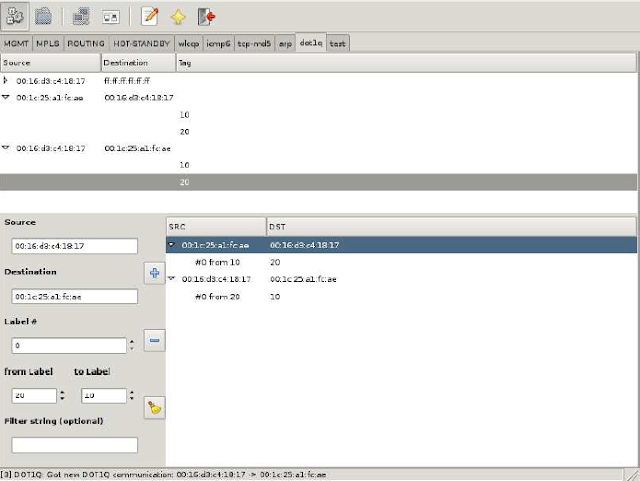
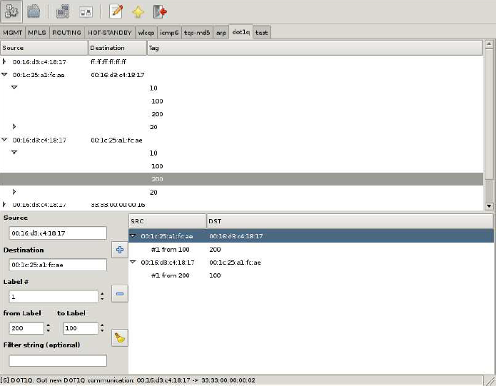
Loki can be used to relabel 802.1Q tagged packets on the fly. Once an attacker is in the traffic path all seen 802.1Q communications are listed in the dot1q module.
To rewrite a label in transmission between two hosts, it simply needs to be selected to fill in most of the fields for the rewrite rule. Only the target label and an optional tcpdump filter to match specific data streams need to be added.
Once the rule is added a background thread takes care of the relabeling.
Modifying Q-in-Q on MPLS Network
The dot1q module in Loki can also be used to rewrite the inner 802.1Q label used in Q-in-Q scenarios in the same way as when rewriting the outer 802.1Q label.
Network behavior with Security Impact, resulting from unified Layer2 Network
If several sites form a common Layer2 domain after connecting them (mainly in “full transparency” cases), some interesting settings – with potentially huge security impact – can emerge.
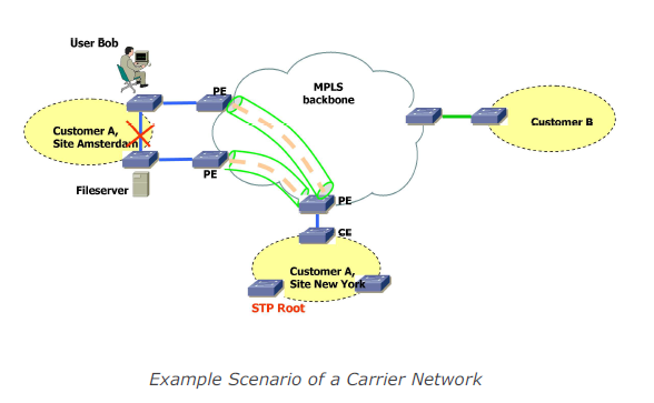
For example, there might only be one Spanning Tree Root in the whole (then worldwide) L2 network (or one per VLAN). Combined with the fact that some sites may even implement redundant links to the carrier network the following scenario might follow:
Here the network traffic resulting from Bob’s access to the fileserver with actually be forwarded to New York and back to Amsterdam (as the link between the switches in Amsterdam is in blocking state), effectively passing the MPLS backbone (possibly unencrypted). Moreover Bob (or the site’s or the company’s security officer) might be completely unaware of this situation.
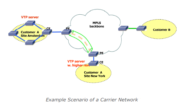
Another example of (at the first glance) “unexpected” network behavior is shown in the following diagram:
With a fully transparent Intra-Site Ethernet connection the switch in New York will propagate it’s VLAN table to the switches in Amsterdam effectively melting down the complete network over there.
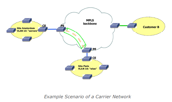
Full transparency with regard to VLANs might impose another risk, shown in the following diagram: “VLAN visibility across the cloud”:
Members of VLAN 10 in Paris (“wlan”) might be able to communicate with members of VLAN 10 in Amsterdam (“servers”), without notice or awareness of the sysadmins in Amsterdam. This is another example of the effects a fully transparent connection may have.
Traditional Layer2 Attacks from One Site to Another
It should be explicitly noted that – in a such a “unified Layer2 network” – the impact of a system compromise in one site may lead to Layer2 attacks against other sites (e.g. attacks against DTP with subsequent sniffing of remote VLANs with yersinia). Previously such attacks mostly probably were not possible.
Misconfigurations on the Carrier Side, leading to Security Breaches of/within Customer Network
If, for instance, the carrier is expected to provide “partial transparency” but actually “full transparency” is implemented (due to operational deficiencies and/or human error), security problems (like those depicted above) may arise.
Another example (which in fact happens) is the accidental connection of sites belonging to different customers or leakage of routing information due to typos in the VRF/VFI identifiers.
Misconfigurations on the Customer Side, leading to Breaches
In “full transparency” scenarios diligent configuration of the customer’s network devices might be necessary to avoid security problems as discussed above. Bad operational practice or human errors may easily lead to severe problems here.
Product or Technology Change on Carrier Side may lead to different Level of Transparency
If the customer is unaware of the exact behaviour of the carrier’s Ethernet service at one point and “just doesn’t notice any problems”, a technology change (be a change of device firmware to a newer version, be a change of an infrastructure protocol’s configuration) may lead to security exposure. A well known historical example was the (mostly unannounced) introduction of a proprietary OSPF enhancement called Link Local Signaling in Cisco’s IOS which effectively broke OSPF sessions with (customer) Nokia devices after (carrier) IOS upgrades some years ago.
Inconsistent Transparency Level amongst “Carrier Ethernet” Product(s) from one Vendor
Carriers offering a nation- or even worldwide Ethernet service may technologically implement the product in different ways, depending on the distance between sites (“Metro Ethernet” in case of regional offices, VPLS if far distance between sites). The different technologies may behave differently then as for the level of transparency.
The Label Distribution Protocol, initially specified in the RFC 3036, is a signaling protocol for distributing labels for a label switched path in an MPLS network. In 2007 RFC 5036 was released and replaces the old specification. LDP serves a set of procedures and messages by which Label Switched Routers (LSRs) establish Label Switched Paths through a network by mapping network routing information to data-link layer switched paths. The procedures consist of four kinds of functions: discovery functions, session management, advertisement and notification.
Trust Model
LDP uses TCP to establish sessions between two LSRs. UDP is used for basic operations like discovery mechanisms which are periodically sent over the network to a well-known discovery port for all routers of a specific subnet. As these are sent to the “all routers on this subnet” group multicast address, with regard to the discovery process all routers on the local link are regarded trustworthy.
Security Controls Inherent to Technology
To protect the authenticity and integrity of LDP messages, LDP supports the TCP MD5 signature options described in RFC 2385. It has to be activated at the LSRs and may protect the messages by validating the segment by calculating and comparing the MD5 digest. To use the MD5 option a preconfigured password on each LSR is necessary.
Abusing LDP
Loki contains a universal LDP module, written in python. It implements the most common used LDP packet and data types and can be used to participate in the LDP discovery process, as well as establish targeted LDP sessions for advanced signaling. If such a targeted session is established, the tool starts a background thread which sends keep-alive packages to hold the connection open and the signaled data valid. To create such signaling data e.g. EoMPLS virtual circuits signaling, the module provides build-in data types which can be merged to the appropriated signaling packet.
An Example for signaling EoMPLS virtual circuits
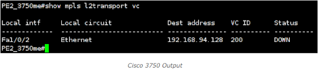
The peer is a Cisco 3750ME was configured, but not activated virtual circuit:
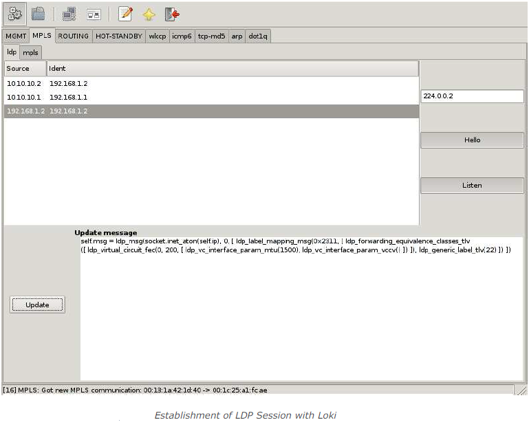
Loki is the used to establish an LDP session and to send the necessary signaling information:
First Loki needs to take part in the LDP discovery process; this is done by activating the Hello-Thread via clicking on the “Hello” button. Next the remote host tries to connect the attacks host via TCP, so Loki needs to listen for that incoming connection; this is done by activating the Listen-Thread via clicking on the “Listen” button. Once the Connection is established, the remote Host will show up in the Host-List. The next step is to configure the LDP update message, which defines the signaling message to publish to the remote host. In this case I generate a LDP Label-Mapping-Message. In the end I send the prepared update message by selecting the designated host from the host list and clicking on the “Update” button.
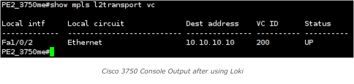
After sending the LDP Label-Mapping-message the configured virtual circuit is activated on the remote side:
So, I activated the virtual circuit and mapped it to a label defined in the update message. A tool like mplstun could be used to set up a valid endpoint on the attacker’s side.
Loki’s MPLSmodule is designed to relabel specified MPLS traffic with a given label. It can be used to manipulate the transport label and change the destination of the packet, or to redirect traffic into another MPLS-VPN. The module automatically detects all MPLS labeled traffic on the wire and let the user easily set up relabeling rules. It is possible to add a tcpdump filter to the relabeling rule, if the module should only redirect some special kind of traffic. Last but not least one can define which label in the label stack should be modified.
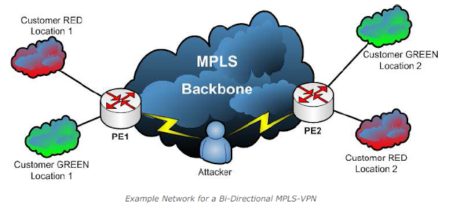
It should be noted that this attack requires that the attacker has access to the traffic path of the respective packets. The setup for this example looks like this:
The attacker is in a Man-in-the-Middle situation inside the data path between Provider Edge 1 and Provider Edge 2 in the MPLS backbone.
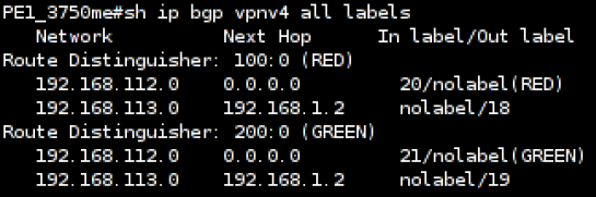
On PE1 the label association for the both MPLS-VPNs looks like this:
Console: Cisco 3750 Label Overview
Which means outgoing traffic for customer RED’s location 2 is tagged with the MPLS label 18. In the other direction, traffic tagged with MPLS label 20 is sent out to customers RED’s location 1. The same for customer GREEN, outgoing traffic for location 2 is tagged with label 19, incoming traffic with label 21 is sent out to location 1. Both customers use the same IP address space for the two locations, which is possible, as I got a logical separation in the routing of each customer.
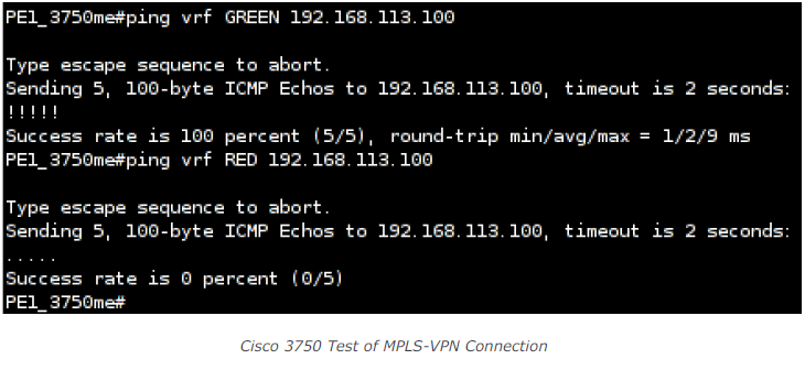
Let’s further assume I got a client with the IP address 192.168.113.100 connected to customer GREEN’s location 2. So, it’s possible to ping this client from PE1 in the context of customer GREEN. I need to specify the virtual routing and forwarding context of customer GREEN to use the customer’s specific routing table. If I run the same command in the context of customer RED, no response will be visible:
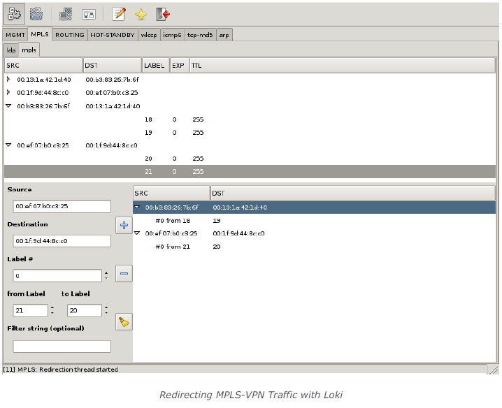
Next the attacker starts to redirect traffic from PE1 to PE2 in the backbone from customer RED’s MPLS-VPN to customer GREEN’s MPLS-VPN and redirect traffic from PE2 to PE1 in the backbone from customer GREEN’s MPLS-VPN to customer RED’s MPLS-VPN by Loki like this:
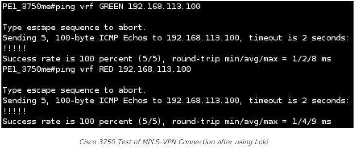
Once the redirection is in place it is possible to ping my assumed host from both, customer RED’s and customer GREEN’s context:
So this actually means that with right position in the traffic path and the right tool (e.g. Loki) an attacker can easily redirect a given site’s traffic of a given customer to a different destination (provided the IP addresses are the same which presumably is a valid assumption when it comes to addresses like 10.1.1.1 or 192.168.10.1).